Purpose / Goal
The goal of this project was to build and document a solar tracking control platform that can adjust panel orientation based on light direction. The project combines Arduino control, light-based sensor input, servo movement, schematic design, and PCB layout practice.
Parts Used
- Arduino-based control board
- Light sensing components
- Servo motor for panel movement
- Solar panel or panel mockup
- Breadboard and jumper wires
- Foam/cardboard prototype structure
- KiCad schematic and PCB layout files
Build Process
The project started with a low-cost physical prototype to test the basic solar tracking concept. The control system uses light sensing to compare light direction and servo movement to adjust the panel orientation.
After the physical prototype was tested, the circuit was documented through schematic drawings and PCB layout work. The schematic and PCB images show the transition from a rough breadboard-style prototype toward a cleaner hardware design.
Challenges
Main challenges included getting stable sensor readings, controlling servo movement smoothly, organizing the wiring, and translating the prototype circuit into a cleaner schematic and PCB layout.
The project also required checking how the sensors, servo, and control logic worked together so the tracker could respond to light direction in a consistent way.
Results / Evidence
The project demonstrated a working solar tracking concept and produced supporting documentation including prototype images, Arduino code screenshots, schematic images, and PCB layout images.
The final documentation shows both the physical build and the electrical design process behind the solar tracking platform.
Project Images
These images show the physical prototype, schematic work, PCB layout work, and Arduino code evidence.
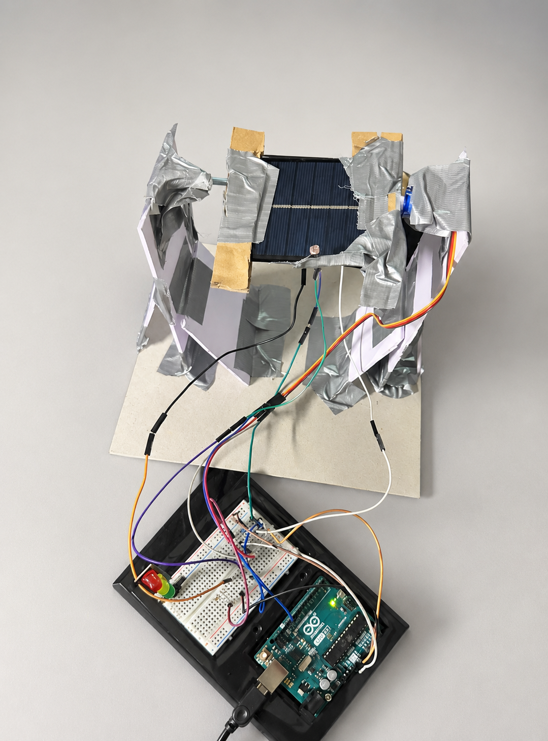
Physical solar tracking prototype build.
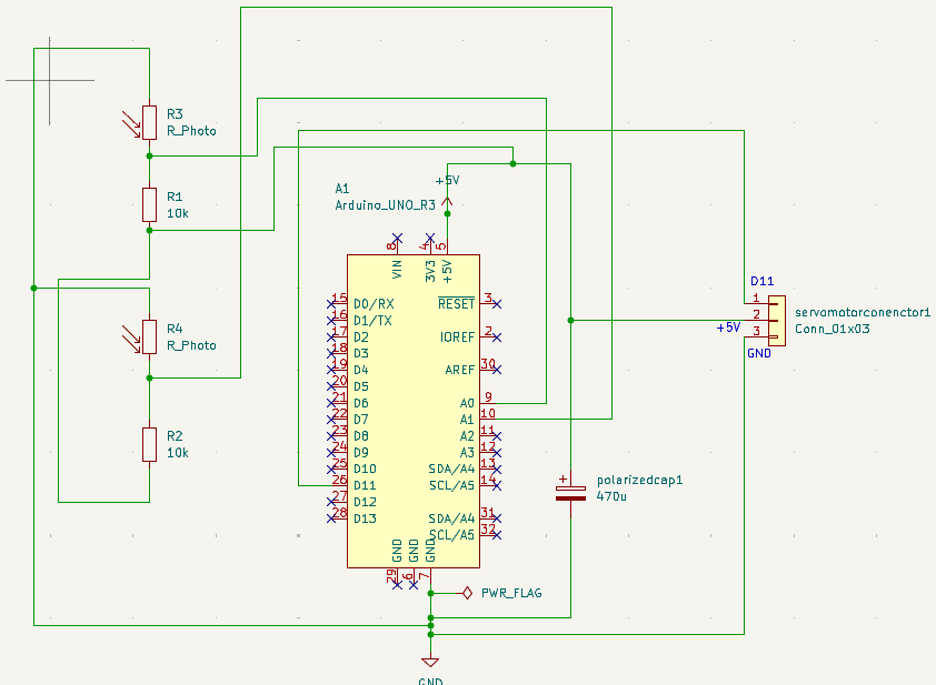
Solar tracker circuit schematic.
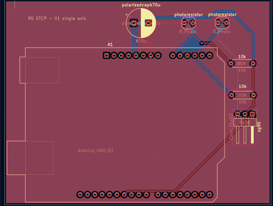
Completed schematic view with circuit connections.
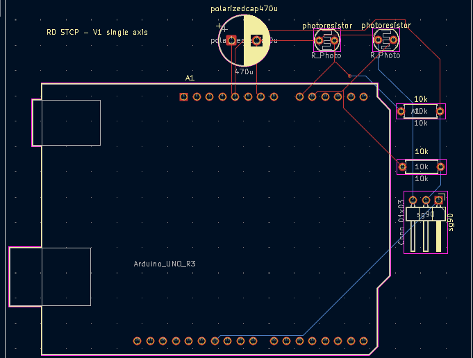
PCB layout view for the solar tracking circuit.
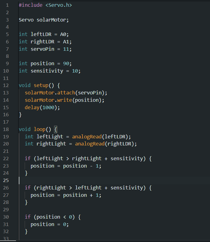
Arduino code for sensor reading and servo control.
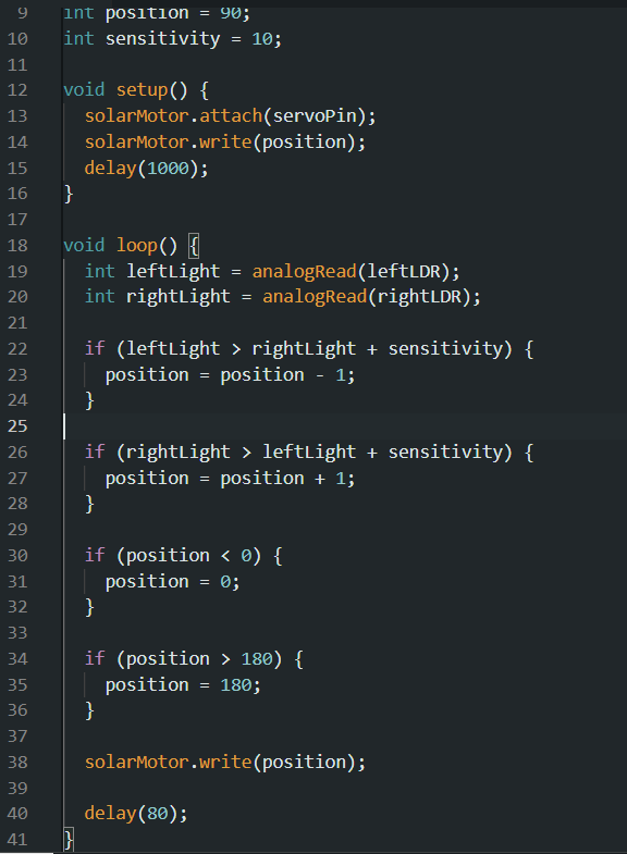
Additional Arduino code for solar tracking logic.
Next Improvements
Future improvements could include a cleaner physical mount, more accurate calibration, better sensor placement, improved code comments, and testing the circuit with a more polished PCB version.