Project Overview
This project implements a three-phase transmission monitoring system built around two physical transmission towers, phase-state sensing, and Arduino-based fault classification. Individual Phase A, B, and C paths can be opened, connected to a grounded common reference, or bridged to one another to create distinct fault conditions. The OLED and LED indicators show the detected condition in real time.
System Capabilities
The project combines a physical transmission structure with phase-state monitoring, fault classification, visual status indication, and early-warning logic. The system monitors and communicates multiple transmission-line conditions in real time.
Goal
Design and validate a physical three-phase transmission monitoring system that can identify multiple fault conditions, communicate phase status clearly, and provide an Early Fault Detection warning before fault confirmation.
Multiple Fault Types
Go beyond a single broken-wire condition by distinguishing open, phase-to-ground, and phase-to-phase faults.
Clear System Status
Use an OLED plus separate normal/fault LED indicators so each phase state is easy to read.
Early Warning Layer
Add an EFD state that can be armed separately and issue warning information before fault confirmation.
Physical Transmission Structure
Create a physical, testable transmission-line structure that can be repeatedly operated and documented.
System Architecture
The physical tower structure supports three phase paths. The Arduino monitors each path, classifies configured fault states, and sends the result to the OLED and phase LED indicators.
Physical and Electronic Hardware
- Arduino Uno R4 WiFi
- Two built transmission towers
- Three phase conductors: A, B, and C
- Two breadboards for phase logic and display/EFD wiring
- OLED I²C status display
- Six LEDs for phase normal/fault indication
- Fault posts for phase-to-ground and phase-to-phase test conditions
- EFD sensor input and an arm/disarm pushbutton
Operating Flow
- The Arduino reads the phase-path states.
- Open, ground-fault, and phase-to-phase conditions are classified.
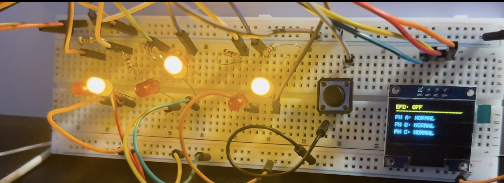
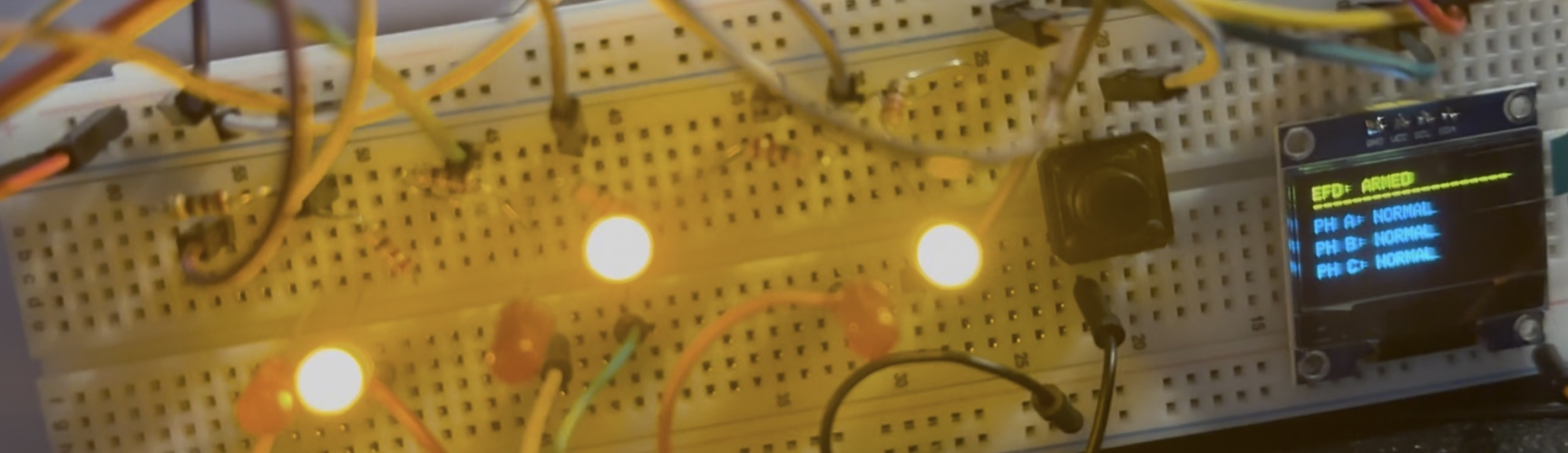
- The OLED labels the detected condition for each phase.
- Green/red LEDs show normal or fault status by phase.
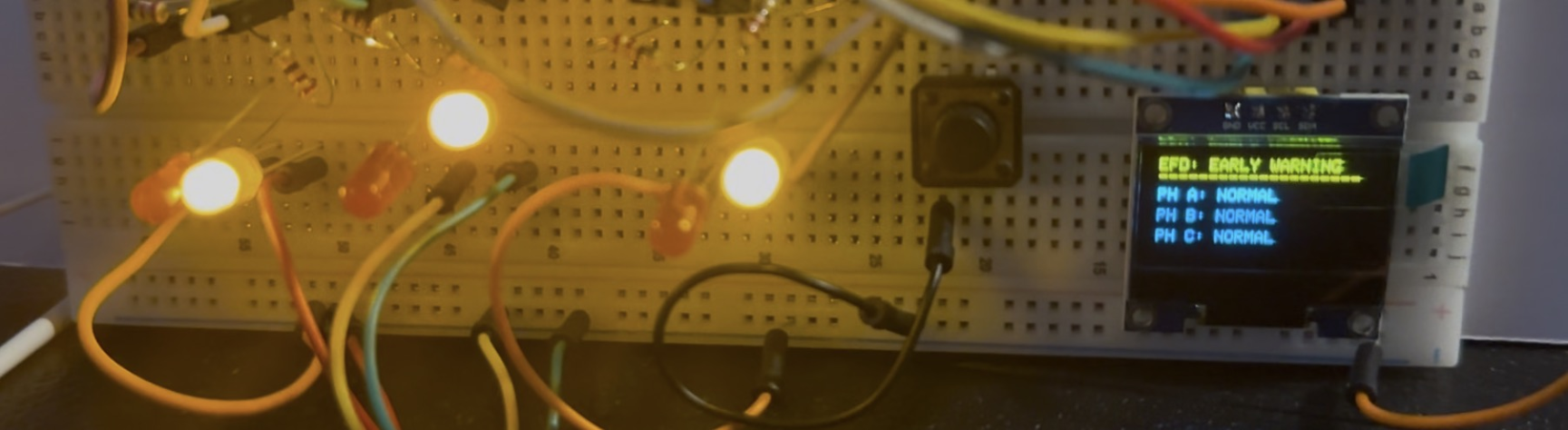
- EFD can be armed independently and latches an early-warning state.
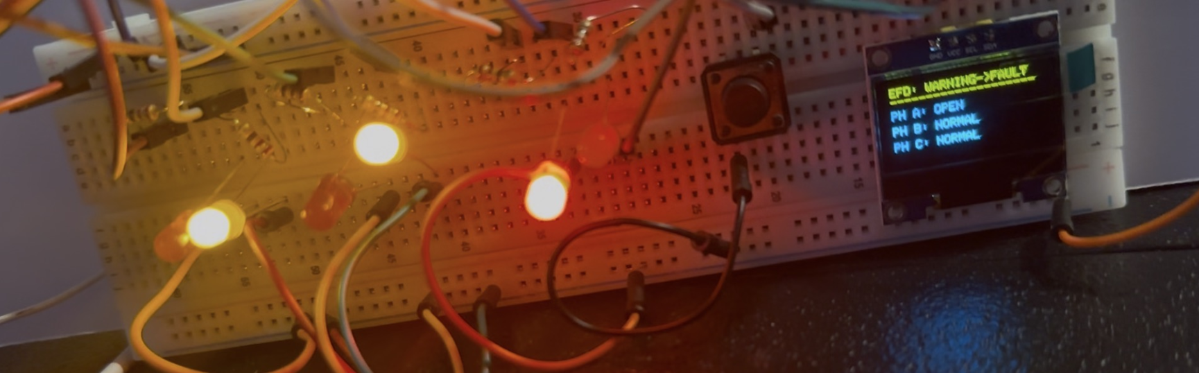
- A later configured fault is shown as a confirmed fault condition.
| Phase sensing inputs | A0 = Phase A, A1 = Phase B, A2 = Phase C |
|---|---|
| Continuity / phase logic reads | D5 = Phase A, D6 = Phase B, D7 = Phase C |
| Phase status LEDs | D8/D9 = Phase A, D10/D11 = Phase B, D12/D13 = Phase C |
| OLED display | I²C connection using SDA and SCL |
| EFD input | A3 monitors the EFD sensor input |
| EFD arm / disarm button | D0 configured with INPUT_PULLUP |
| Ground-fault reference | Arduino GND/common reference used as the phase-to-ground return path |
Build Process
The project was developed in stages so the physical structure, phase logic, user display, and Early Fault Detection behavior could each be tested before final documentation.
Construct the Transmission Structure
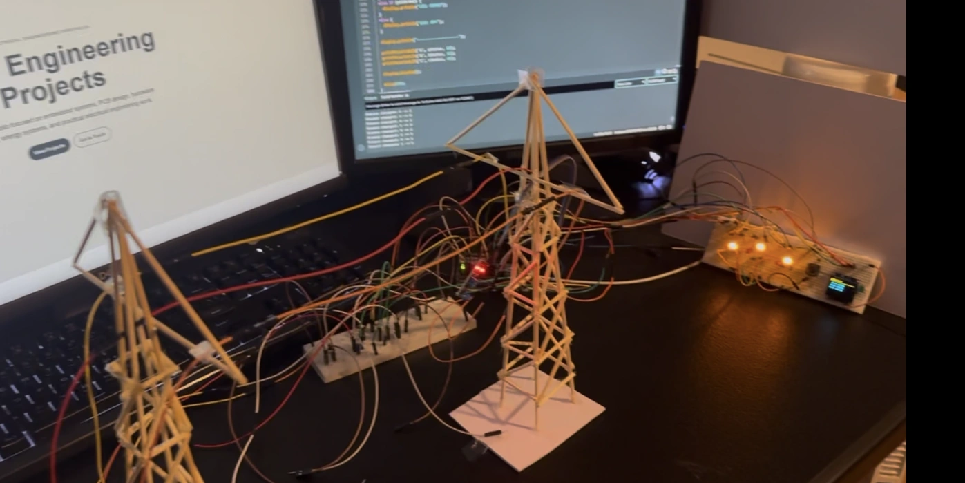
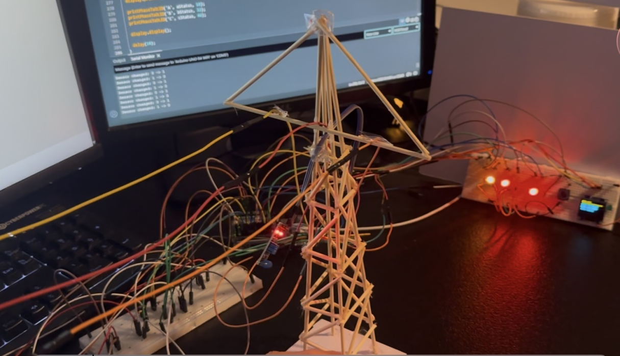
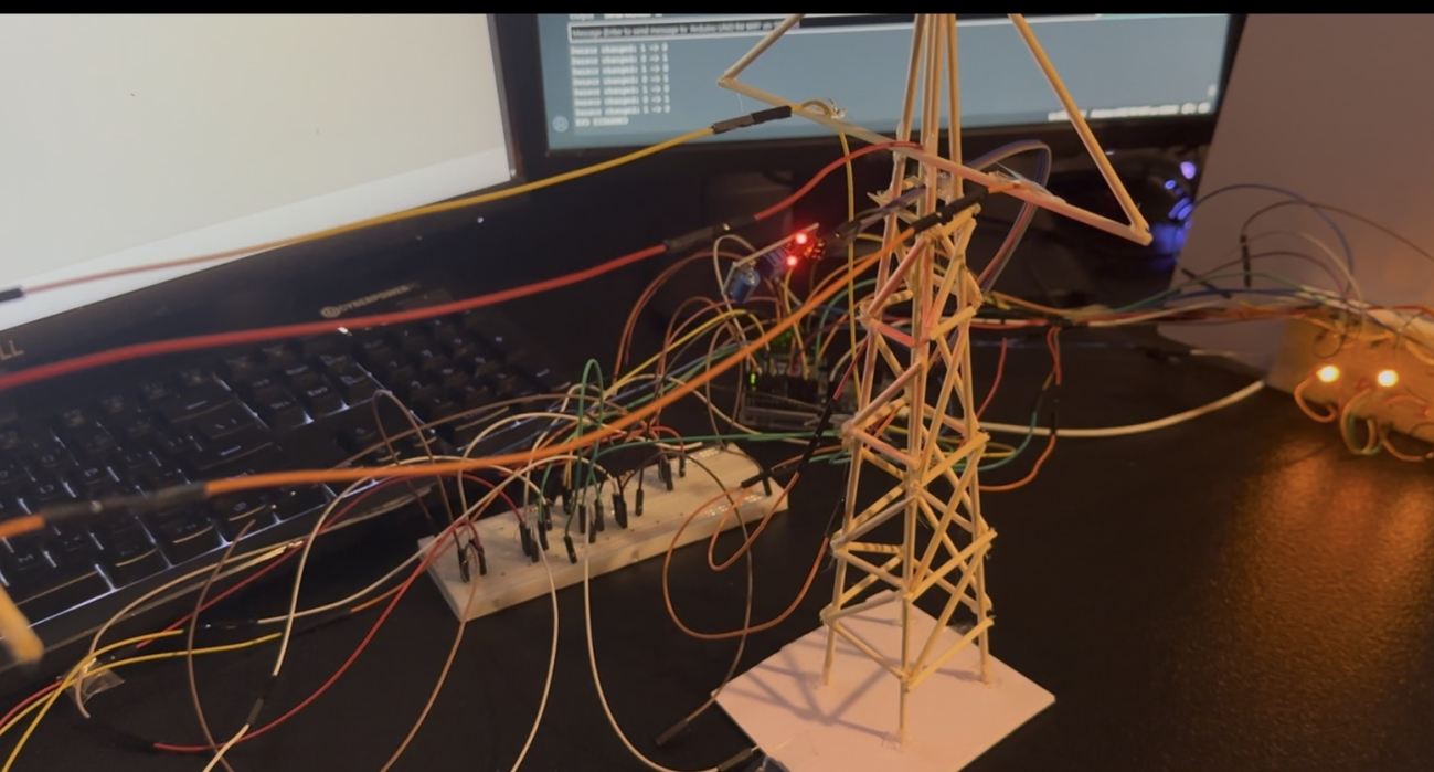
Two transmission towers were built on a foam base and interconnected with three overhead phase conductors.
Create the Phase Monitoring Paths
Each phase received a separate sensing path with an accessible connection point for repeated fault testing.
Add Visual Status Outputs
An OLED display and six phase LEDs were connected so normal and fault conditions could be shown immediately.
Add Fault-Post Test Connections
Configurable fault-injection connections enabled repeated phase-to-ground and phase-to-phase testing without rebuilding the system.
Implement Early Fault Detection
The EFD input and arm/disarm button were added as a separate warning layer from the phase-fault classification logic.
Program and Test the System
Arduino code was expanded and tested through normal operation, individual faults, combined faults, and EFD sequence behavior.
Fault Detection and EFD Logic
The system separates phase-fault classification from the EFD warning state so an early warning can be displayed before a configured fault condition is confirmed.
Open-Phase Logic
A broken or disconnected phase path is identified as an open condition for the affected phase.
Phase-to-Ground Logic
Connecting a phase to the grounded common reference produces the associated A-G, B-G, or C-G fault state.
Phase-to-Phase Logic
Bridging two phase posts creates a phase-to-phase condition such as A-B, B-C, or C-A.
EFD State Handling
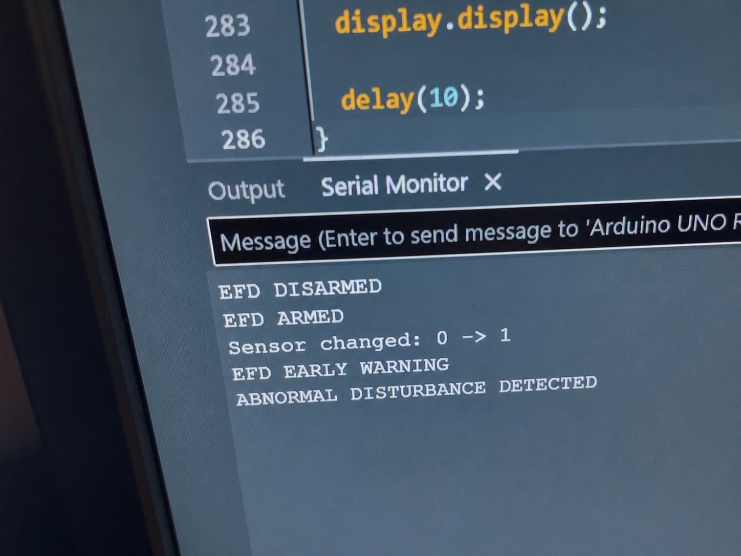
When EFD is armed, an EFD sensor event latches the early-warning state while phase monitoring continues independently.
Challenges and Engineering Decisions
Making Fault States Distinct
The logic had to distinguish open phases, phase-to-ground conditions, and phase-to-phase conditions without accidentally treating different connection states as the same fault.
Building a Testable Physical Structure
The towers and conductors needed to look like a transmission line while still allowing the phase paths and fault posts to be accessed repeatedly during testing.
Communicating Information Clearly
The OLED and LEDs were used together so the system could provide a readable text status and immediate phase-by-phase visual indication.
Separating Warning From Confirmation
EFD was designed as an early-warning layer that remains separate from confirmed phase-fault classification, which makes the state sequence easier to interpret.
Results and Evidence
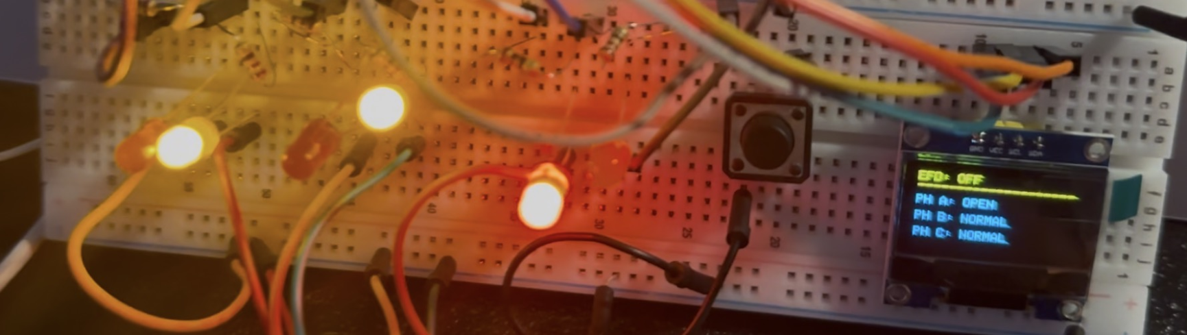
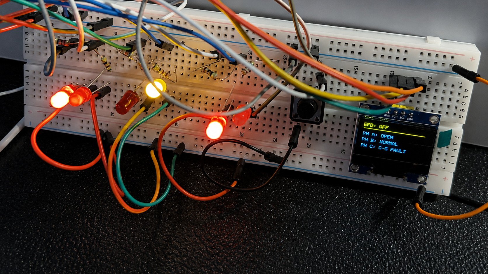
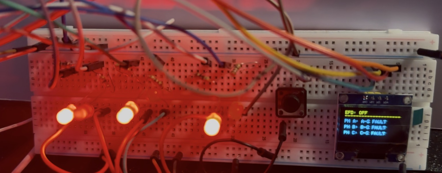
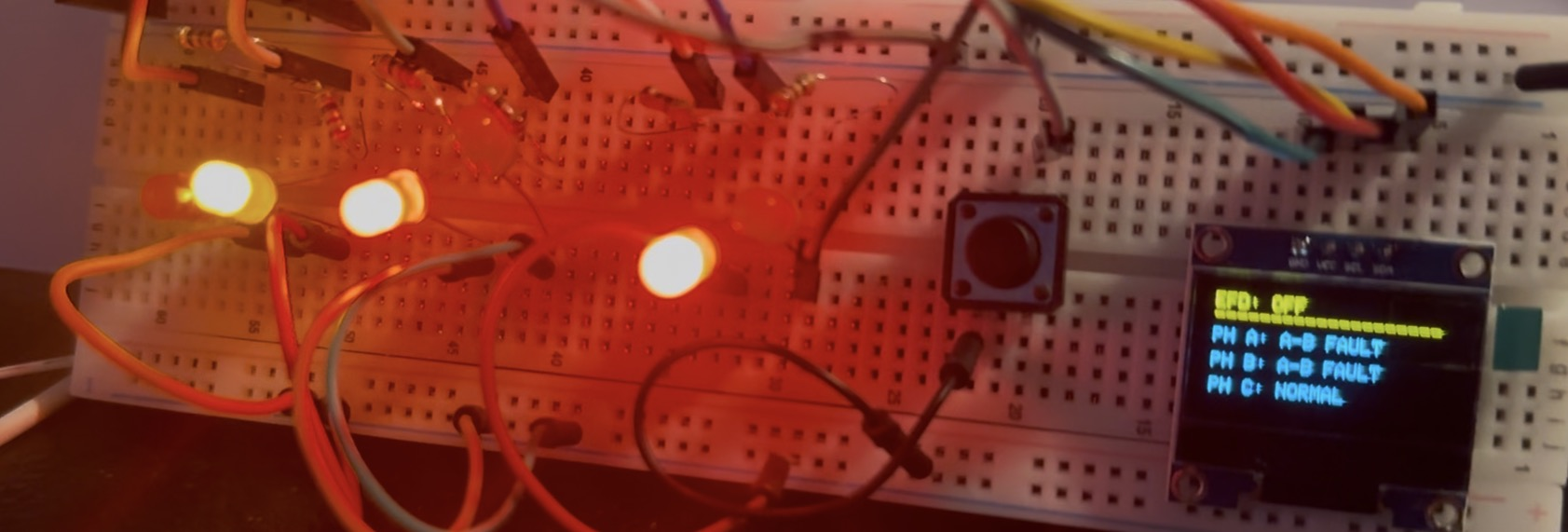
The completed build was tested through a sequence of physical phase connections and system states.
Build and Test Gallery
Physical build photos and recorded system states from normal operation, fault tests, EFD states, and serial-monitor evidence.
Engineering Documentation Under Development
The physical system has been completed and tested. Formal engineering documentation is being developed to capture the wiring architecture and final Arduino implementation.
Formal Schematic
A complete schematic is being prepared for the phase-sensing paths, fault posts, OLED, status LEDs, EFD input, pushbutton, and Arduino connections.
Source Code Release
The final Arduino source code is being prepared for release with organized comments and supporting documentation for phase monitoring, fault logic, display output, and EFD state handling.
Next Improvements
Future improvements could include cleaner wire routing and more secure phase and fault-test connections, clearer labels at the test points, a more rigid tower base, and expanded fault-event logging.